Off-Grid Solar Power Design Mistakes: A Fault Guide
Diagnose dawn shutdowns, PoE reboots, weak recharging and heat failures with practical checks for batteries, MPPT controllers and site loads.
By Maxsol Team

The most common off grid solar power system design mistakes become visible as repeatable symptoms: equipment shuts down before sunrise, PoE devices reboot, batteries never reach full charge, outages appear during less favourable weather, or components fail inside hot enclosures. The fastest way to isolate the fault is to measure energy flow and voltage at the time of failure—not simply install a larger panel or battery.
Use the symptom, likely cause, measurement and correction sequence below as a structured investigation. All scenarios are hypothetical and should not be treated as a diagnosis of any actual installation.
Fault-isolation table for common solar system failures
| Symptom | Likely design cause | What to measure or verify | Possible correction |
|---|---|---|---|
| System shuts down shortly before dawn | Insufficient usable battery energy, excessive overnight load, voltage drop or an early low-voltage cut-off | Battery-terminal voltage under load, controller load-output voltage, overnight current, cut-off event logs and cable voltage drop | Reduce the night load, correct cable sizing, review cut-off settings within battery limits, increase usable storage, or restore sufficient daily charging |
| Camera, access point or radio repeatedly reboots | Startup surge, battery voltage sag, undersized converter, PoE incompatibility, long cable loss or loose connections | Converter input and output during startup, peak load, connector voltage, polarity, pinout, PoE mode and voltage at the powered device | Use a correctly rated and compatible converter, shorten or resize cables, correct termination, or separate high-startup loads |
| Battery fails to recharge fully | Array energy is insufficient, panel is shaded, MPPT input is mismatched, load consumes charging energy, or battery protection blocks charging | PV voltage and current, daily load energy, controller limits and logs, battery temperature, charging state and shading pattern | Remove avoidable shade, correct the array-controller match, reduce daytime demand, increase recharge capacity, or address battery protection conditions |
| Outages occur only during wetter or lower-sun months | Design was based on annual-average sunshine rather than the least favourable operating period | Site-specific design-month solar input, consecutive low-generation days, seasonal shading and daily energy balance | Recalculate for the design month, add appropriate generation or storage margin, or reduce non-critical loads |
| Equipment becomes unstable in a hot enclosure | Thermal derating, blocked airflow, solar heat gain, battery charging-temperature limits or heat-damaged connections | Internal enclosure temperature, device alarms, current at peak temperature, ventilation condition and terminal resistance | Improve shading and heat management, follow component temperature limits, reposition heat sources, or use equipment suited to the enclosure conditions |
Measurements should be taken by competent personnel using safe procedures and instruments appropriate to the system voltage and fault current.
Mistaking nominal power and energy for usable supply
Watts and watt-hours answer different questions:
- Watts (W) describe the power being drawn or produced at a particular moment.
- Watt-hours (Wh) describe energy accumulated or consumed over time.
- Amp-hours (Ah) are meaningful only when the battery voltage is also known.
A continuous 18W load, for example, consumes 432Wh over 24 hours:
18W × 24 hours = 432Wh
This is a hypothetical arithmetic example, not a measured product runtime. The actual system must also supply conversion losses, cable losses, startup demand and any loads omitted from the 18W assumption.
Likewise, dividing nominal battery energy by a device’s nameplate wattage does not establish dependable autonomy. Battery protection cut-offs, reserve margin, temperature, battery condition, discharge current and converter efficiency all reduce the energy that reaches the equipment.
Do not compare batteries by Ah alone
A 12V-class battery and a 24V-class battery can have very different stored energy even when both carry the same Ah figure. Convert each option to nominal Wh first:
Nominal energy in Wh = nominal voltage × Ah
Then estimate usable delivered energy separately. Do not assume the complete nominal figure is available at the load.
For further battery-selection context, see the practical explanation of LiFePO4 battery benefits and limitations for solar CCTV.
Product labels are inputs, not runtime promises
Two Maxsol solar-system examples illustrate why each specification must be read in context:
| Selection example | Documented panel | Documented battery | Other documented features |
|---|---|---|---|
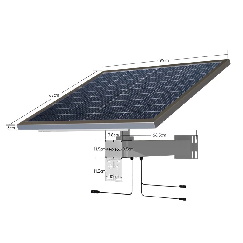
| CS8040 80W and 45Ah solar system | 80W monocrystalline | 12.8V 45Ah, 576Wh LiFePO4 | MPPT controller, three DC12V outputs; RS485 optional |
| CS12060 120W and 60Ah solar system | 120W monocrystalline | 12.8V 60Ah, 768Wh LiFePO4 | MPPT controller, three DC12V outputs; RS485 optional |
These nominal specifications do not establish universal autonomy or a 24/7 operating guarantee. The larger figures may provide more generation and storage on paper, but suitability still depends on the real load profile, design-month solar conditions, conversion path, reserve requirement and installation environment.
The products are selection examples rather than a tested compatible bundle with every camera, radio or PoE converter. Confirm the current datasheet and supplied configuration before final design.
Sizing for average sunshine instead of the design month
Annual-average sunshine can make an energy balance look comfortable while hiding failure during prolonged cloud, wetter periods or seasonally unfavourable shading. For an unattended Malaysian site, the design should focus on the least favourable period in which the system is still expected to meet its operating requirement.
This does not mean guessing a universal “sun-hours” value for Malaysia. Solar access varies by site, horizon, panel orientation, nearby vegetation, buildings and weather pattern. Use a relevant site dataset and document the source and design period.
The basic daily balance is:
Required PV energy ≥ load energy + system losses + battery recovery requirement
A common mistake is sizing the panel only to supply one normal day of load. After a low-generation period, the array must support the active equipment while also replacing energy removed from the battery. If almost all daytime generation is consumed by the load, the battery may remain partially charged even when the controller appears to be operating normally.
Check recharge time, not only autonomy
A large battery can delay the first outage but may make recovery harder if the panel remains undersized. Review both directions of the energy balance:
- How long can the battery support the essential load within the intended reserve?
- How much surplus PV energy remains for recharging while the load is running?
- How many suitable charging periods are needed to recover from the design discharge?
- Can the controller and battery accept the required charging power within their limits?
For the underlying calculation method, use this guide to sizing an off-grid solar power system for CCTV, then apply conservative, site-specific assumptions rather than annual averages.
Omitting night loads, conversion loss and startup demand
A load survey must include every operating mode, not just the camera or radio’s daytime nameplate value. Frequently missed loads include:
- CCTV infrared illumination after dark
- Pan-tilt-zoom movement, heaters or auxiliary illuminators
- Wireless radio transmission peaks
- PoE conversion and DC conversion losses
- Network switch, router, modem or recording equipment
- Controller and monitoring consumption
- Enclosure fans or other thermal-management equipment
- Startup and reconnection surges
- Cable losses on long DC and Ethernet runs
Night loads deserve separate attention because they operate when the solar panel contributes little or no useful energy. A camera that draws more power after infrared LEDs activate can move the highest load into the longest battery-only period.
Measure at more than one point
Measuring only the current leaving the battery may not reveal where a reboot begins. During commissioning, capture:
- Battery-terminal voltage
- Controller load-output voltage
- Converter input voltage
- Converter output voltage
- Voltage at the end device
- Steady-state and startup current
If the battery remains above its cut-off but the voltage at the converter collapses, the fault may be in the cable, connector, fuse or controller output. If the converter input remains stable but its output falls, investigate converter limits or load compatibility.
Use logged minimum and maximum readings or an instrument capable of capturing short events. A standard multimeter display may miss a brief startup sag that is long enough to restart a radio.
Mismatching battery, MPPT and PoE interfaces
Correct energy sizing does not guarantee electrical compatibility. The battery, panel array, MPPT controller, converter and powered device must operate within one another’s voltage, current, power, polarity and protocol limits.
Battery and MPPT checks
Verify the current datasheet and supplied configuration for:
- Permitted PV open-circuit voltage
- MPPT operating-voltage range
- Maximum PV input current and power
- Supported battery voltage and chemistry
- Charging-voltage profile
- Battery-management-system behaviour
- Battery charging-temperature limits
- Controller load-output current
- Low-voltage disconnect and reconnect behaviour
- Protection devices and cable requirements
Do not connect panels merely because their total wattage appears suitable. Series wiring increases voltage, while parallel wiring increases current. Either arrangement can exceed a controller limit if it is not calculated correctly.
A system that “fails to recharge” may therefore have enough nominal panel wattage but an array voltage outside the MPPT operating range. It may also be limited by the controller, battery protection or charging conditions.
PoE voltage is not the same as PoE compatibility
A powered device may require standards-based detection and negotiation, a particular passive PoE voltage, a specific polarity or a defined pinout. An adjustable output labelled for PoE should not be assumed compatible with every IP camera, wireless bridge or access point.
The POE24V DC-to-PoE converter accepts 12–36V DC and provides an adjustable 12–57V PoE output, Gigabit Ethernet and an LCD voltage display. Its documented continuous load for 12V-to-48V conversion is at most 30W.
The stated conversion efficiency of up to 94% is a maximum, not a guaranteed design value. IEEE powered-device detection or negotiation is not established by the approved product facts. Before connection, verify:
- Powered-device input-voltage range
- Required passive or standards-based PoE method
- Polarity and pin assignment
- Maximum startup and continuous power
- Converter input voltage under worst-case battery conditions
- Cable voltage drop
- Earthing and surge-protection arrangement
Do not test compatibility by trial and error on production equipment. An incorrect voltage, pinout or polarity can damage the powered device.
Ignoring shading, temperature and maintenance access
Solar faults are often treated as electrical sizing problems even when the root cause is physical installation.
Shading must be checked across time
A panel that appears clear at midday may be shaded in the morning, late afternoon or during a different part of the year. Partial shade from poles, antennas, cabinet doors, roof edges or growing vegetation can materially reduce energy harvest.
Record the shading pattern for the relevant design period. Also check whether future vegetation growth, new equipment or changed antenna positions could obstruct the panel.
Enclosure temperature affects the complete power chain
Outdoor enclosures can experience substantial solar heat gain. High internal temperature may reduce converter capability, increase cable and connector resistance, trigger protective functions or place the battery outside permitted charging conditions.
Do not assume that a large cabinet is automatically cool enough. Review:
- Direct solar exposure
- Cabinet colour and external shading
- Internal equipment spacing
- Heat-source placement
- Ventilation or approved cooling method
- Water and insect ingress implications
- Manufacturer temperature limits
- Cable and terminal condition at operating temperature
Any ventilation change must preserve the environmental protection needed by the site.
Inaccessible equipment becomes an operational risk
Mounting the battery, controller or fuses where they cannot be safely inspected encourages delayed maintenance and incomplete measurements. Provide practical access to:
- Isolation and protection devices
- Battery and controller terminals
- Status indicators and displays
- Communications ports
- Cable glands and earth connections
- Replaceable parts
- Test points
Labels should identify cable destination, voltage, polarity, protection rating and isolation sequence. If RS485 monitoring is needed, confirm that the selected product configuration includes the optional interface and that it can be integrated with the intended monitoring system.
Validate the corrected design with a commissioning checklist
A corrected calculation should be proven by measurements before the site is left unattended. Commissioning should cover normal operation, startup behaviour and credible low-energy conditions.
Load and energy checks
- Confirm every daytime and night-time load.
- Activate infrared illumination, radio transmission and other high-demand modes.
- Measure steady-state and startup power.
- Record daily energy use where suitable logging is available.
- Confirm that non-critical accessories are included in the energy budget.
- Compare measured load with the design assumptions.
PV, controller and battery checks
- Verify array wiring, polarity and electrical limits.
- Check for shading during relevant operating periods.
- Confirm controller settings for the supplied battery.
- Record charging voltage, current and controller state.
- Verify low-voltage cut-off and reconnect behaviour without exceeding battery limits.
- Confirm that the battery can recharge while the normal daytime load remains active.
- Review charging-temperature restrictions and protection behaviour.
PoE and cable checks
- Confirm powered-device voltage, protocol, polarity and pinout.
- Measure converter input during startup and at low battery voltage.
- Measure voltage at the powered device, not only at the cabinet.
- Check long cable runs for excessive loss.
- Confirm converter continuous and startup capacity.
- Inspect terminations, fuses and connectors for heating or looseness.
Environmental and maintenance checks
- Measure enclosure temperature under representative operating conditions.
- Ensure equipment has suitable spacing and heat management.
- Confirm that drainage, cable glands and ventilation are not obstructed.
- Make isolators, fuses, indicators and test points safely accessible.
- Label the shutdown and restart sequence.
- Save baseline readings so future maintenance teams can identify changes.
A successful short daytime test does not prove overnight autonomy or recovery after low-generation weather. Record the assumptions that cannot be fully tested during commissioning and establish an appropriate monitoring or follow-up plan.
The practical next step is to compare the linked Maxsol solar-system and converter examples against the project’s actual port count, load, transmission distance, power demand, environment and management requirements. Confirm every electrical interface and the current supplied configuration before treating the components as a complete system.