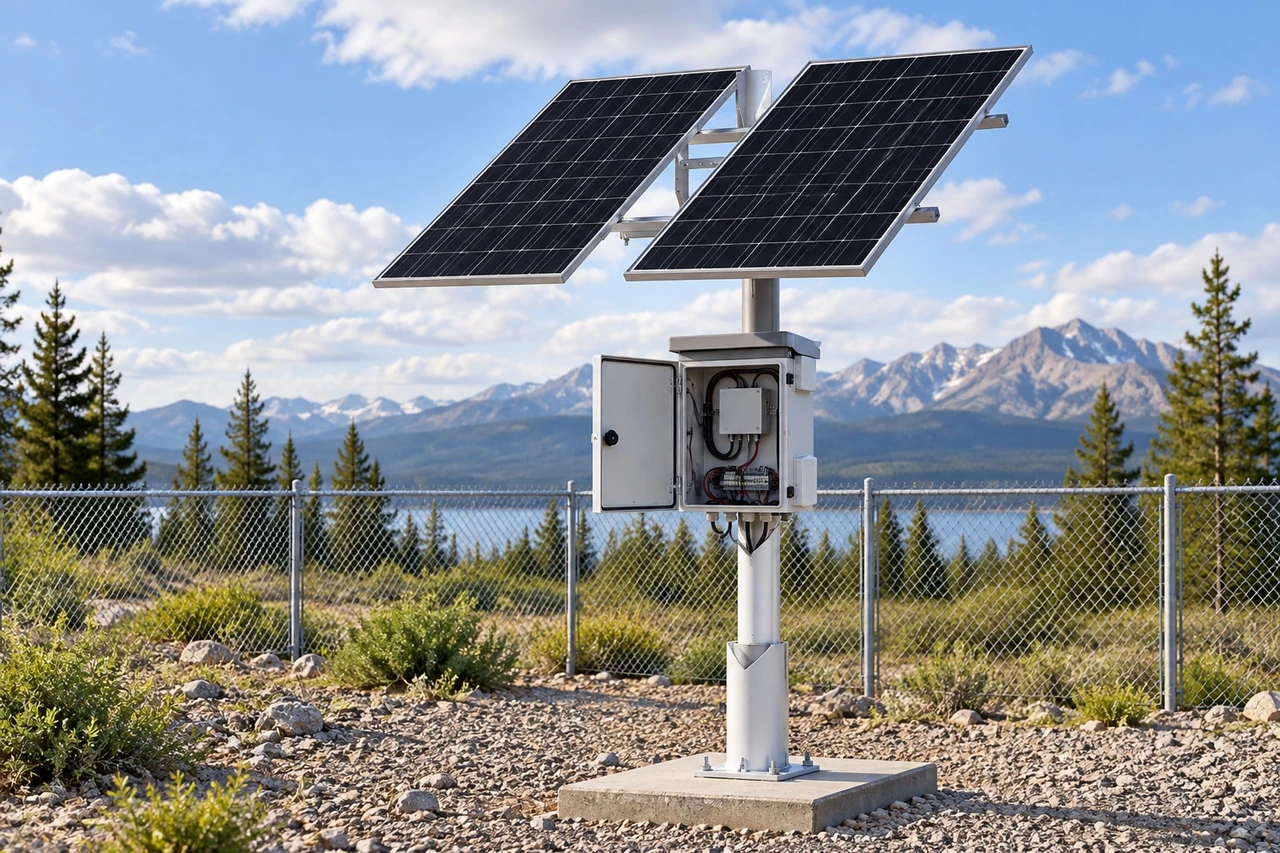
5 Key Factors for Choosing an Outdoor Solar Power System
Compare five factors before buying an outdoor solar power system: verified load, solar access, battery autonomy, installation and future expansion.
By Maxsol Team

Choosing an outdoor solar power system starts with five checks: the verified electrical load, solar access during the design month, battery autonomy under expected temperatures, outdoor installation requirements, and capacity for future expansion. Panel wattage and battery capacity alone are not enough to determine whether a system will operate reliably at a specific site.
For projects in Malaysia, buyers should compare suppliers using site-specific evidence rather than a generic package label. Ask for a documented load schedule, shading assessment, energy assumptions, interface diagram, installation plan and expansion limits. Any runtime estimate should clearly state the conditions behind it.
1. Verify the load and electrical interfaces
The first factor is not the solar panel. It is the equipment that must be powered, including its actual operating profile and connection requirements.
A security or wireless site may include:
- Fixed, PTZ or infrared cameras
- Wireless access points or CPE bridges
- Industrial Ethernet or PoE switches
- Cellular routers and communication gateways
- Sensors, relays, illuminators or other auxiliary devices
- DC converters, PoE injectors and protection accessories
Record the continuous load, peak load and operating hours for every device. Do not rely only on a product’s nominal rating. A camera may draw more power when infrared illumination, heaters, motors or other functions are active. Wireless equipment may also have different startup and peak consumption from its typical operating figure.
Questions to ask before comparing systems
Request clear answers to the following:
- What is the measured or datasheet maximum power draw of each device?
- Which loads operate continuously, and which operate intermittently?
- Is there a startup surge or temporary peak?
- What losses have been allowed for in the controller, cabling and voltage conversion?
- Will the load change at night or during poor weather?
- Are additional devices likely to be connected later?
A supplier should show how the total daily energy requirement was obtained. If a proposal only states that a system can support “one camera” or “several devices”, it is not sufficiently specific. Camera types, wireless radios and network equipment can have substantially different loads.
For a detailed calculation process, use this off-grid solar sizing guide for CCTV systems. Buyers still need to validate all assumptions against the selected equipment and site.
Confirm voltage, polarity and port compatibility
Electrical interfaces are just as important as total power. Confirm:
- Required input voltage and acceptable voltage range
- DC connector type, size and polarity
- Number of independent outputs
- Maximum current per output and for all outputs combined
- Whether the load requires direct DC, passive PoE or standards-based PoE
- Whether a converter, injector or splitter is required
- Cable length and the resulting voltage drop
- Earthing, isolation and surge-protection arrangement
A DC12V output cannot be assumed to power a PoE device directly. If conversion is required, include the converter’s own power consumption and limits in the design. Also verify that cable voltage at the load remains within the device’s permitted range during peak demand.
The same principle applies when selecting solar power for outdoor security cameras: match the complete camera and network configuration, not just the camera count.
2. Assess design-month solar access and shading
Solar capacity should be assessed against the most demanding practical operating period, not the annual average. The design month is the period when expected solar energy is lowest relative to the site load and required service level.
Malaysia’s outdoor conditions can include extended cloud cover, heavy rain, high humidity and rapid vegetation growth. Their impact varies by location and season, so buyers should not accept an unexplained national solar-hours figure as proof that a system is correctly sized.
Ask for site-specific solar evidence
A useful assessment should identify:
- The data source used for estimated solar energy
- The month or period selected for design
- Panel direction and tilt assumptions
- Horizon obstructions around the installation
- Shading at different times of day
- Expected losses from temperature, dirt, wiring and conversion
- The recovery assumption after several low-solar days
Annual average irradiation can make a proposal look comfortable while hiding weak performance during the design month. Ask the supplier to show both the expected daily load and the conservative solar energy available during the selected period.
Treat partial shading as a design issue
A small shadow is not always a small loss. Trees, poles, antennas, buildings and security fencing can shade part of a panel or one panel in a multi-module configuration. The effect depends on panel arrangement, controller design and the timing of the shadow.
Before installation, inspect the solar window throughout the day. Consider not only current obstacles but also:
- Future tree growth
- New site structures
- Parked vehicles or machinery
- Antennas added to the same pole
- Dirt from nearby roads or industrial activity
- Access needed for panel cleaning
Photos, a sun-path survey or a site model are stronger evidence than a general statement that the location is “open”. Where the survey is conducted during only one season, account for changes in the sun’s path during the rest of the year.
An oversized panel cannot fully compensate for persistent shading if the underlying site layout is poor. Moving the array or load enclosure may be more effective than increasing nominal wattage.
3. Match battery autonomy, temperature and protection
Battery autonomy is the period for which stored energy can support the load without sufficient solar charging. It should be treated as a design assumption, not a universal promise.
A basic comparison begins with battery energy in watt-hours, but nameplate capacity is not the same as energy delivered to the equipment. Actual usable energy depends on the permitted depth of discharge, controller cut-off settings, temperature, conversion losses, battery condition and load profile.
Compare autonomy on equal assumptions
When reviewing proposals, ask each supplier to state:
- Battery chemistry and nameplate energy
- Permitted discharge limits
- Controller low-voltage disconnect setting
- Continuous and peak load used in the calculation
- Conversion and cable-loss assumptions
- Temperature range used for the estimate
- Number of low-solar days considered
- Conditions required for the battery to recharge
Without this information, two quoted autonomy figures may not be comparable. One may use a typical load and nearly all nameplate energy, while another may use maximum load and a more conservative discharge limit.
No system should be assumed to provide universal 24/7 operation solely because it uses a large battery. Runtime always depends on the site load, available solar energy, system settings and environmental conditions.
Account for enclosure temperature
Outdoor battery temperature can differ substantially from the surrounding air temperature, especially when an enclosure is exposed to direct sun or has inadequate ventilation. High internal temperature can affect batteries, controllers and networking equipment. Charging behaviour can also be subject to temperature limits.
For a LiFePO4 system, confirm:
- Permitted charging and discharging temperatures
- Whether temperature sensing is included and where it is located
- How the controller responds outside permitted charging conditions
- Enclosure ventilation and solar exposure
- Separation between heat-generating components
- Battery-management and overcurrent protection arrangements
Do not assume that an outdoor-rated enclosure automatically maintains a suitable internal operating temperature. Placement, colour, ventilation, loading and direct solar exposure all influence the actual conditions inside it.
Protection should also be reviewed as a coordinated system. Confirm fuse or breaker locations, cable ratings, reverse-polarity measures, short-circuit response, low-voltage disconnection and the safe isolation procedure for maintenance.
4. Plan outdoor mounting, cabling and maintenance
An outdoor solar system is only as dependable as its physical installation. Mounting strength, cable routing, water management and service access can determine whether the equipment remains practical to operate.
The installation plan should cover the panel array, battery and controller enclosure, load equipment, cable paths, grounding arrangement and maintenance access. These elements should be reviewed together rather than purchased as unrelated components.
Panel and enclosure mounting
Ask the installer or supplier to document:
- Pole, wall or ground-mounting method
- Structural loads and mounting-point requirements
- Panel orientation and adjustment range
- Corrosion considerations for fasteners and brackets
- Enclosure position relative to direct sunlight and flood risk
- Protection against accidental contact, theft or vandalism
- Safe access for inspection and cleaning
A convenient mounting location is not necessarily a good solar location. Conversely, the clearest solar position may create long cable runs, difficult maintenance access or higher exposure to physical damage. The final layout should balance all these factors.
Cable routing and protection
Outdoor cable design should consider voltage drop, current, distance and exposure. Confirm the conductor size and calculate voltage at the equipment rather than checking only the controller output.
Good installation planning normally addresses:
- UV and weather exposure
- Suitable cable glands and strain relief
- Drip loops before enclosure entries
- Separation of power and data where required
- Mechanical protection against sharp edges and movement
- Labelling at both ends of each cable
- Earthing and surge-protection paths
- Disconnect points for safe maintenance
Protection requirements vary by site. Elevated poles, open fields, building rooftops and exposed perimeter installations can present different risks. The responsible project designer should determine the appropriate earthing and surge-protection approach for the complete system.
Define routine maintenance before purchase
Maintenance should not be an afterthought. Establish who will inspect the system, how often access is possible and which readings or conditions will be checked.
A practical maintenance plan may include:
- Removing dirt, leaves and bird droppings from panels
- Checking for new shading or vegetation
- Inspecting brackets, fasteners and cable supports
- Examining glands, seals and drainage points
- Checking terminals for looseness or corrosion
- Reviewing controller status and battery data
- Verifying that the connected load has not changed
- Recording faults, shutdowns and configuration changes
Ask whether diagnostic data can be viewed locally or remotely, what tools are required and how faults are identified. A design that is difficult to inspect can increase troubleshooting time even if its electrical sizing is correct.
5. Consider lifecycle support and expansion
The final factor is whether the selected system can support changes during the project lifecycle. Additional cameras, a higher-power radio or a replacement switch can make the original energy design inadequate.
Build an expansion allowance based on plausible changes, but do not simply attach more equipment because spare connectors are available. Every added load affects daily energy demand, battery autonomy, controller capacity, cable current and recharge time.
Check the expansion limits
Before purchase, confirm:
- Spare power outputs and their electrical limits
- Total controller load capacity
- Maximum supported solar input
- Battery configuration and permitted expansion method
- Space for converters, injectors or protection devices
- Enclosure thermal capacity after extra equipment is added
- Network port count and management requirements
- Whether firmware, configuration tools and replacement parts can be supported
- Which changes require the system to be redesigned
Battery or panel expansion is not always a plug-and-play exercise. Mixing batteries of different specifications or conditions can introduce technical and safety concerns. Adding panels may exceed controller input limits, while a larger battery may take too long to recover with the existing array. Obtain written confirmation for the intended configuration.
Use product sizes as comparison points, not guarantees
Documented Maxsol configurations illustrate how panel, battery and output count change across system scales:
- The CS6030 60W and 384Wh solar system documents a 60W monocrystalline panel, 12.8V 30Ah 384Wh LiFePO4 battery, MPPT controller and three DC12V outputs.
- The CS12060 120W and 768Wh solar system documents a 120W monocrystalline panel, 12.8V 60Ah 768Wh LiFePO4 battery, MPPT controller and three DC12V outputs.
- The CS400150 400W and 1920Wh solar system documents two 200W panel modules, a 12.8V 150Ah 1920Wh LiFePO4 battery, MPPT control and four DC12V outputs.
These are scale examples rather than guaranteed matches for an unspecified load or Malaysian site. A larger listed panel and battery do not remove the need to verify the design-month energy balance, output current, voltage compatibility, controller limits, charging temperatures and protection. Confirm the current datasheet and supplied configuration before selection.
Support should also be evaluated in practical terms. Ask what documentation is supplied, how configuration changes are handled, which components are replaceable and what information is needed for fault diagnosis. Commercial terms, warranty coverage and replacement arrangements should be confirmed directly because they can vary by product and transaction.
Five-factor supplier comparison checklist
Use the same project information for every supplier. Otherwise, one proposal may appear more economical simply because it excludes losses, poor-weather assumptions or installation components included by another.
| Factor | Evidence to request | Questions for comparison | Warning signs |
|---|---|---|---|
| Verified load and interfaces | Device list, load schedule, peak demand, connection diagram and voltage-drop calculation | Are all continuous, night-time and startup loads included? Are DC and PoE interfaces compatible? | Sizing based only on device count or nominal panel wattage |
| Design-month solar access | Solar data source, selected design period, panel orientation and shading assessment | Does the calculation use a conservative month? Have obstructions and system losses been included? | Reliance only on annual averages or an unverified “sun hours” figure |
| Battery autonomy, temperature and protection | Battery energy, discharge limits, controller settings, thermal assumptions and protection diagram | What load and temperature are used for runtime? How does the system recover after low-solar days? | Guaranteed runtime without stated conditions |
| Outdoor installation and maintenance | Mounting layout, cable plan, enclosure arrangement, access method and maintenance schedule | Who is responsible for structure, earthing, surge protection, cleaning and inspection? | No cable-loss calculation or unclear responsibility for installation details |
| Lifecycle support and expansion | Port and controller limits, expansion rules, documentation and support scope | Can planned equipment be added safely? Which changes require redesign? | “Expandable” claims without electrical or configuration limits |
The strongest proposal is not necessarily the one with the largest panel or battery. It is the one that makes its assumptions visible, matches the required interfaces, addresses the site’s difficult solar period and explains how the installation will be maintained.
As a next step, compare the linked Maxsol models against your required port count, verified load, cable distance, power interfaces, outdoor environment and management needs. Then validate the current datasheet, supplied configuration, controller limits, charging temperatures and protection before finalising the system.