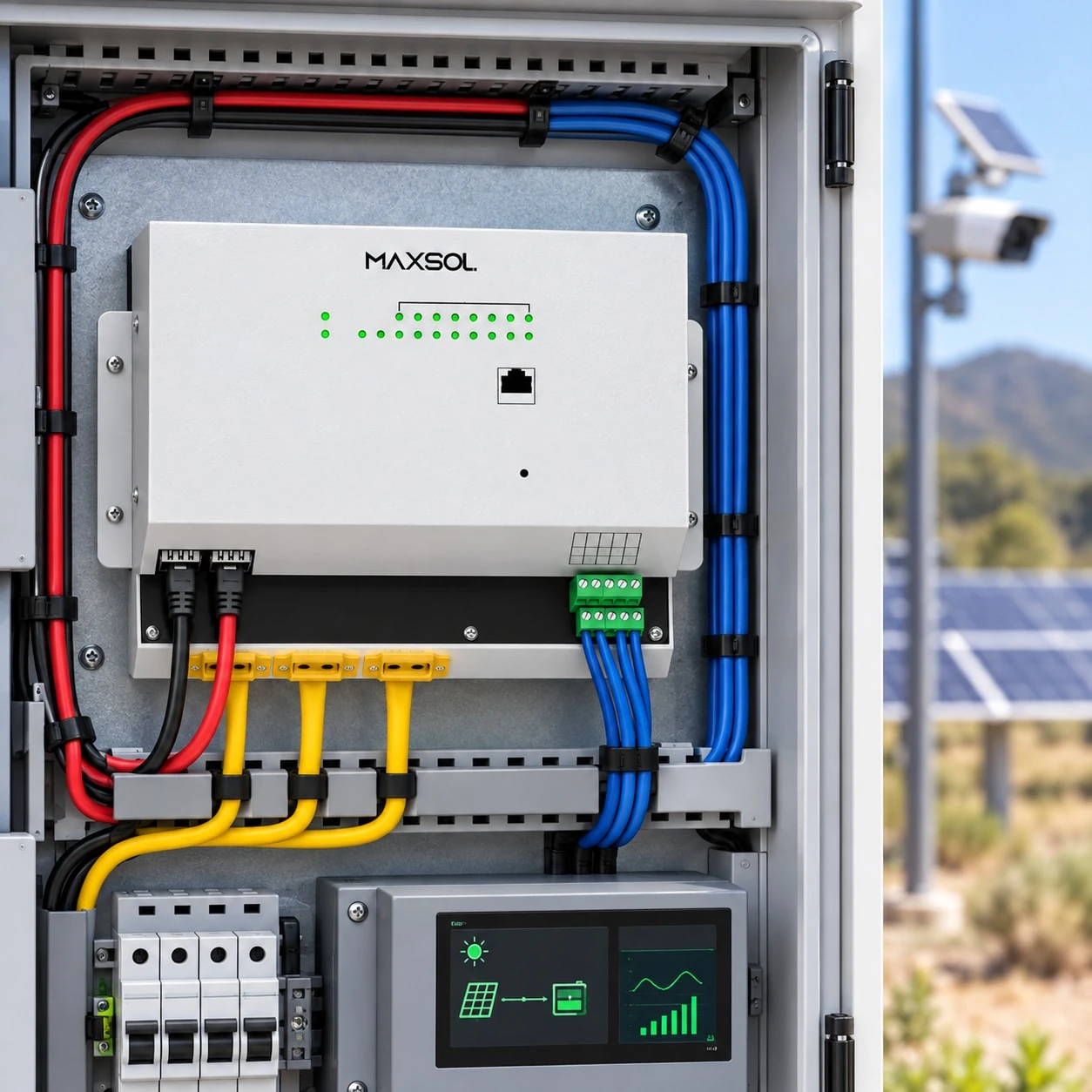
Building a 24/7 Solar-Powered Network Off Grid
Learn how to size power, storage, PoE, wireless backhaul and recovery controls for a reliable remote solar-powered network in Malaysia.
By Maxsol Team

A 24/7 solar-powered network for remote locations must be engineered as a complete energy and communications system, not assembled by matching headline wattages. Start with the services that must remain available, measure every continuous and temporary load, then size the battery and solar array against the site’s worst solar month and required recovery period.
The design also needs managed PoE distribution, a suitable backhaul, automatic load shedding, controlled restart logic, remote monitoring and a practical maintenance plan. Continuous operation remains an engineering objective rather than a universal product promise: actual performance depends on site-specific sunlight, shading, temperature, radio conditions, equipment settings and maintenance.
Define network services and an availability objective
Before choosing panels, batteries or switches, define what the remote site must do. A surveillance location, plantation Wi-Fi link, perimeter camera point and environmental monitoring station may all use similar equipment, but they do not have the same service priorities.
List the required services in operational terms:
- Video recording at the site
- Live camera access from a control room
- Wireless backhaul to another location
- Local Wi-Fi access
- Sensor or alarm transmission
- Remote equipment management
- Auxiliary lighting or warning devices
- Maintenance access to logs and diagnostics
Then classify each service by priority. A practical three-tier model is:
| Priority | Service behaviour during low energy | Typical examples |
|---|---|---|
| Tier 1: Essential | Remains powered for as long as the design allows | Core router, critical camera, alarm link, system controller |
| Tier 2: Operational | May be reduced or temporarily disconnected | Secondary cameras, local access point, non-critical sensors |
| Tier 3: Deferrable | Switched off first and restarted last | Lighting, convenience Wi-Fi, maintenance-only equipment |
An availability objective should specify more than “24/7”. Record:
- The services that must remain active overnight
- The low-solar period the battery must bridge
- Which loads may be shed during an energy shortage
- How quickly the system should recover after sunlight returns
- Whether local recording must continue if the backhaul fails
- What constitutes a reportable outage
- How technicians will access the site if remote recovery fails
Avoid assigning an uptime percentage unless the design includes the data, redundancy, monitoring and maintenance process needed to support it. For many projects, a clear operational statement is more useful—for example, “keep the essential network tier active through the specified low-harvest period, then restore secondary loads only after battery recovery”.
Inventory continuous, intermittent and startup loads
A reliable load schedule separates equipment by how and when it consumes power. Using only each device’s maximum label rating can result in an oversized system, while using optimistic average figures can leave the site without enough storage.
Continuous loads
These operate throughout the day and usually determine the base energy requirement:
- PoE switch electronics
- Router or gateway
- Wireless backhaul radio
- Cameras configured for continuous operation
- Network video recorder or edge storage device
- Solar controller and monitoring electronics
- DC converters and protection equipment
For each item, record its normal measured input power, maximum expected power, operating voltage and hours of operation.
Intermittent loads
Some devices change consumption according to time, traffic or environmental conditions:
- Infrared camera illumination after dark
- Pan-tilt-zoom movement
- Heaters, fans or cabinet ventilation
- Alarm sounders
- Site lighting
- Cellular transmission bursts
- Maintenance sockets or temporary equipment
These loads need a duty-cycle assumption. The assumption should be conservative and documented so it can be checked during commissioning.
Startup and peak loads
Startup current may be brief, but it can trigger a controller, converter or protection device if the peak exceeds its limit. Check:
- Simultaneous PoE device startup
- Radio boot-up
- Motor movement in PTZ cameras
- Infrared illuminators activating together
- DC converter inrush
- Recovery after a complete low-voltage shutdown
Sequence high-demand devices where possible rather than starting everything at once.
Build the daily energy budget
For each load:
Daily energy in Wh = operating power in W × operating hours
Add continuous and intermittent energy, then account for losses between the solar array and the final powered device. These can occur in the controller, battery, wiring, DC conversion, PoE conversion and network equipment.
Do not treat battery nameplate energy as energy that can always be delivered to the loads:
- Nominal energy is the battery’s voltage multiplied by its rated ampere-hours.
- Usable battery energy is the portion permitted by operating limits and the battery management system.
- Usable delivered energy is what remains at the devices after wiring and conversion losses.
Cable length matters as well. Excessive voltage drop can make equipment reset even when the battery still contains energy. Check conductor size, cable distance, connector resistance, current and the minimum permitted input voltage of every device.
For a detailed camera-focused approach, see the solar PoE switch guide for remote IP camera networks.
Size worst-month storage, solar and recharge capacity
Solar sizing should use site-specific conditions for the most difficult operating period, not an annual average. In Malaysia, cloud cover, heavy rain, heat, vegetation growth and local shading can materially affect harvest and equipment conditions. Obtain suitable solar resource information for the precise site and assess obstacles at the planned panel position.
Size storage around the required bridge period
Battery storage must cover the selected load tiers for the required low-harvest period. The basic design relationship is:
Required delivered storage = protected daily load × required bridge duration
The nominal battery must then be larger than the delivered requirement because discharge limits, conversion losses, temperature conditions and ageing allowances affect the available energy.
Define two storage cases:
- Normal operating case: all intended loads run according to their schedules.
- Energy-conservation case: only essential loads remain active after thresholds are reached.
This makes the system’s behaviour predictable. It also prevents a non-critical load from exhausting energy needed for the backhaul or primary camera.
As one architecture reference, the Maxsol CS400150 400W and 1920Wh solar system documents a 400W panel configuration using two 200W modules, a 12.8V 150Ah 1920Wh LiFePO4 battery, MPPT control and four DC12V outputs. These are nominal product details, not a runtime guarantee. Suitability depends on the measured site load, usable delivered energy, solar input, controller limits and required reserve.
Size the array for operation and recovery
The array must do more than cover the current daytime load. After a poor solar period, it also needs enough surplus energy to recharge the battery while the network remains operational.
The daily solar energy requirement therefore includes:
- Energy used by the network during the day
- Energy needed to replace overnight battery discharge
- Conversion and charging losses
- Additional recovery energy following low-harvest days
- A design allowance based on the project’s uncertainty and operating conditions
A system can have enough storage to survive one difficult period but still fail operationally if the array cannot restore that storage before the next one.
Model recovery explicitly:
- Start at the chosen low battery threshold.
- Apply the assumed worst-month solar harvest.
- Keep essential network loads operating.
- Calculate how much charging energy remains.
- Determine when secondary loads may safely restart.
- Repeat the model across consecutive poor-harvest days.
Panel orientation and placement should also support safe maintenance. Check for future tree growth, mud splash, leaf accumulation, bird fouling, roof shadows and structures that may create new shading.
Common sizing and integration problems are covered in off-grid solar power design mistakes to avoid.
Design PoE switching, backhaul and load priority
The network architecture must match the energy strategy. A large battery cannot compensate for an unmanaged switch that keeps every non-critical device powered until the battery protection system disconnects the entire site.
Select the PoE switch as a control point
Check the following before specifying a switch:
- Number and speed of copper ports
- Required SFP or uplink interfaces
- Total PoE budget
- Maximum requirement of each powered device
- Supported PoE mode and voltage
- Switch input voltage range
- Management and remote diagnostic features
- VLAN, loop control and restart capabilities required by the project
- Environmental installation and enclosure requirements
The Maxsol IOT2802SFG-S managed solar industrial PoE switch documents eight Gigabit PoE ports, two SFP ports, a 120W PoE budget, 90W BT support, PV and battery monitoring, and configurable 24V or 48V PoE on ports 3–4. Its documented PV and battery input is DC22–29.2V.
That input detail is critical: the documented 12.8V CS400150 kit is not a direct compatible input for a DC22–29.2V device. The linked products illustrate alternative architecture components, not a validated bundle. Do not connect them together without confirming voltage architecture, controller limits, interfaces, protection and any required conversion stage.
Also confirm that the planned PoE device combination remains within the total budget. A switch supporting a high-power port does not mean every port can simultaneously provide its individual maximum.
Choose the backhaul based on the real path
A remote site may use fibre, cellular or point-to-point wireless backhaul. Compare them according to access, terrain and operational needs:
| Backhaul | Main advantage | Important checks |
|---|---|---|
| Fibre | Stable high-capacity connection where infrastructure is practical | Route, termination, surge exposure, civil work and repair access |
| Cellular | No remote radio endpoint required | Site coverage, antenna placement, data plan, network variability and router power |
| Point-to-point wireless | Useful where a clear radio path exists | Line of sight, Fresnel clearance, alignment, interference, mounting and endpoint power |
The Maxsol CPE295 5.8GHz wireless CPE documents 5.8GHz operation, a 2×2 14dBi directional MIMO antenna, one Gigabit LAN port and 6.5W full-load consumption. Its suitability cannot be decided from distance alone. Verify the complete radio path, local interference, alignment, mounting stability, Ethernet interface and power method.
Apply priority at the port level
Where the switch and control architecture permit it, assign each powered device to an energy tier. A sensible shutdown order might be:
- Disconnect auxiliary lighting.
- Disconnect convenience Wi-Fi.
- Disconnect secondary cameras.
- Preserve the primary camera, controller and backhaul.
- Shut down the remaining system in a controlled manner before the battery reaches its protection limit.
Use hysteresis between shutdown and restart thresholds. Without it, a load may repeatedly switch on and off as the battery voltage briefly recovers.
Monitor energy, faults and controlled recovery
Remote monitoring should explain both network and energy conditions. A simple “online/offline” indicator is not enough to diagnose whether a failure comes from the radio path, a PoE device, low battery energy or a tripped protection device.
Useful monitoring points include:
- PV voltage and charging state
- Battery voltage and relevant controller status
- Load current or power
- PoE port state
- Switch and backhaul reachability
- Device restart history
- Low-energy and overcurrent events
- Cabinet temperature where relevant
- Repeated link changes or packet loss
- Time since the last successful remote report
Set alarms to give operators time to act. A warning threshold should occur before the automatic load-shedding threshold, which in turn should occur before final battery protection disconnects the site.
Plan a controlled restart sequence
When solar energy returns, do not immediately reconnect every load. A staged process reduces simultaneous startup demand and protects the recovery reserve:
- Confirm stable controller and battery conditions.
- Start the core switch or control layer.
- Restore the backhaul.
- Verify remote management connectivity.
- Start the essential camera or sensor group.
- Observe load and battery response.
- Restore secondary devices after a defined recovery threshold.
- Restart deferrable loads last.
Include retry limits. A faulty PoE camera that continuously restarts should not consume the site’s remaining energy indefinitely. The management plan should isolate the affected port, log the fault and preserve the core network where possible.
Test handover and maintain the remote site
Commissioning should prove the design logic, not merely show that the equipment powers on during a sunny afternoon.
Run a hypothetical worst-month acceptance test
A useful acceptance test can simulate the design’s stated worst-month conditions without claiming that the test predicts universal uptime.
Use this process:
- Measure the final installed load. Record normal, night, peak and startup consumption with the actual configuration.
- Apply the project’s low-harvest assumption. Limit or simulate charging according to the solar input used in the design model.
- Start from the defined battery condition. Use the agreed normal or reduced state rather than an arbitrary full charge.
- Operate the planned service schedule. Include infrared operation, wireless traffic and other timed loads.
- Trigger energy thresholds. Confirm that Tier 3 and Tier 2 loads disconnect in the correct order.
- Verify essential services. Check that the protected network tier behaves as specified.
- Restore the simulated solar input. Confirm that charging supports the active essential loads.
- Observe staged recovery. Ensure devices restart in sequence rather than simultaneously.
- Test individual failures. Disconnect the backhaul, interrupt a PoE device and simulate a controller alarm.
- Record the results. Compare measured behaviour with the acceptance criteria established during design.
The pass criteria must come from the project’s energy model and service objective. They should not be replaced with a generic runtime or uptime claim.
Prepare the site for maintenance
Remote installations still require physical service. Design access before handover:
- Label every cable, fuse, breaker, port and polarity
- Keep an updated wiring and network diagram
- Record device settings and approved firmware baselines
- Provide safe panel and cabinet access
- Document shutdown and restart procedures
- Specify cleaning and inspection intervals based on site conditions
- Check cable glands, seals, mounting hardware and signs of water entry
- Inspect for corrosion, pests, vegetation and physical damage
- Keep suitable replacement protection parts and preconfigured critical spares
- Record battery and controller alarms during every visit
Spares should reflect the site’s failure impact and travel difficulty. Possible items include fuses, surge protection modules, connectors, injectors or converters, a configured radio, and a compatible switch. Confirm exact part compatibility rather than assuming visually similar components are interchangeable.
Final design checklist
Before approving a 24/7 solar-powered network for a remote location, confirm that:
- Every continuous, intermittent and startup load is documented
- Nominal battery energy is separated from usable delivered energy
- Solar sizing uses site-specific worst-month assumptions
- The array has enough recovery capacity, not only daily operating capacity
- PoE port demand fits within the total switch budget
- Battery, controller, switch and load voltage ranges are compatible
- The wireless path has been assessed for clearance and interference
- Essential and deferrable loads have defined priorities
- Low-energy alarms occur before automatic shutdown
- Restart logic is staged and includes retry limits
- Acceptance tests verify low-harvest and recovery behaviour
- Drawings, settings, spares and maintenance access are ready for handover
As a practical next step, compare the linked Maxsol architecture examples against your required port count, measured load, radio distance, voltage and power design, installation environment, and management functions. Verify every interface and controller limit independently rather than treating the products as a pre-approved system bundle.